 |
|
 |
|
Author, Designer and Project Maintainer:
Stephen Manley - smanley@nyx.net
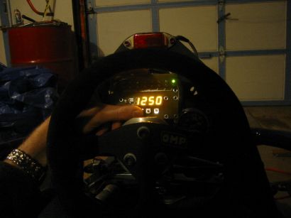
After (years) of mucking about with this, I finally put together a really slick tach that I've had in use for a long time. PCBs are available to experiment with, the source code and schematics are open, the code is well tested and mature, so what are you waiting for?
Check out my new Atmel AVR LED Digital Tachometer!
|
|
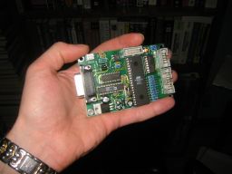
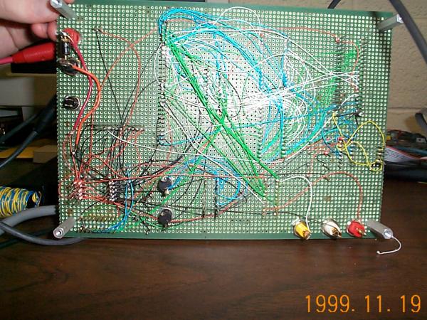
Original, oldschool board layout provided for my own amusement and archival purposes.. I still can't believe I wire wrapped that together and made it work. Fortunately, embedded technology and my own resources have gotten a lot better over the years.
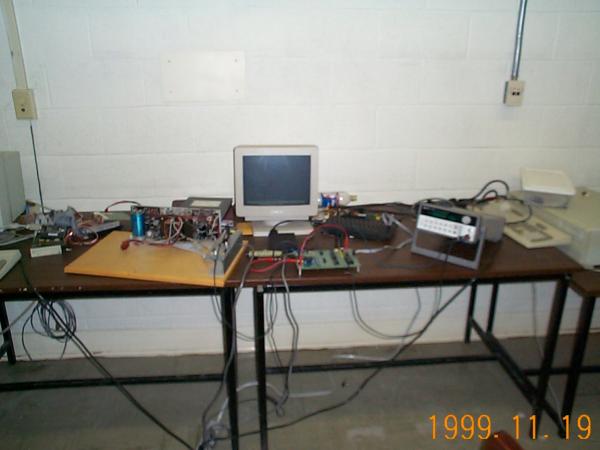
Screenshots & Construction Photos
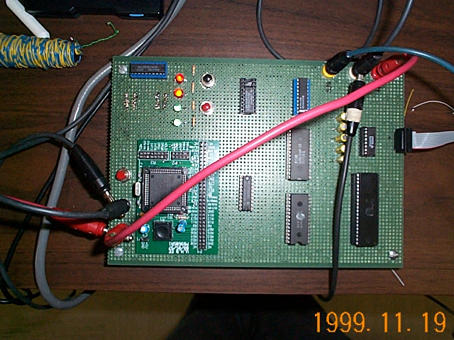
Embedded Computer Design
The board has the following components as is. You probably need the schematic and the board layout to get anywhere.
Interface board
Either transistor or optical to generate ADC compatible voltage levels. See appendix for various schematics. These are basically frequency to voltage converters. This adapts the input to the LM2917 chip or 555 system. The design is flexible. See interfacing specifications for compatible voltage ranges for ADC conversion. (Under development)
2 x SPST Normally Open Switches & Switch Debouncer (Inverter)
Primarily used for debugging. User interaction occurs through a sophisticated serial interface which has the option of providing a interface mode such that other graphical client software can be run to provide a graphical, rendered set of controls.
4 LEDs - 2 Red, 2 Green
Used to indicate board activity, program flow, and alarm conditions.
Main Computer Board
X86 Compatible CPU, Memory and Bus arhitecture Any CPU which supports DMA, and has a C compiler and a 8 bit bus can probably be used.
8256A IO/Controller Serial and Parallel IO Ports
Required to output data to user and/or read switches. This is the primary means of interaction with the user.
0820 - Generic High Speed ADC chip (1Msamples/sec)
Converts voltage into a suitable digital signal for software processing.
EEPROM Expandibility
This allows for quick reprogramming of the board so that options can be changed by the client if they so desire and have access to the proper equipment.
Single Board Computer Design
I'm working on a solution that can work on a PC104 spec single board computer, either running linux or with a custom EEPROM. I'll keep updates here.
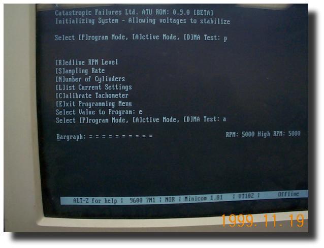
Operating and Programming
The device turns on automatically when power is supplied to the unit, through a power toggle switch. Once voltages are allowed to stabilize the unit will prompt you with a test, configuration and calibration, and active mode option menu. It is trivial to adapt this to send a string to a client such as a palmpilot for offboard processing and logging (the embedded design I have here is limited; A single board computer is a much better choice).
Download
Grab the original source code & makefiles. Code is written under a linux 2.x derivative and will probably compile best under such. This includes all the interface code, embedded code, etc that I have written to date.
 Last Edited: 03/20/06