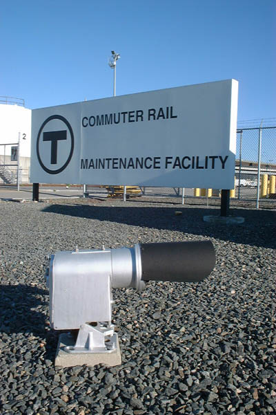
This is the prototype, as seen at the Boston Engine Terminal. This unit is a product of the General Railway Signal Company.
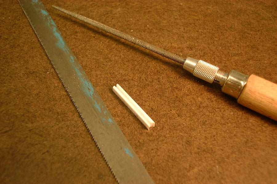
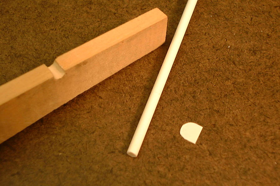
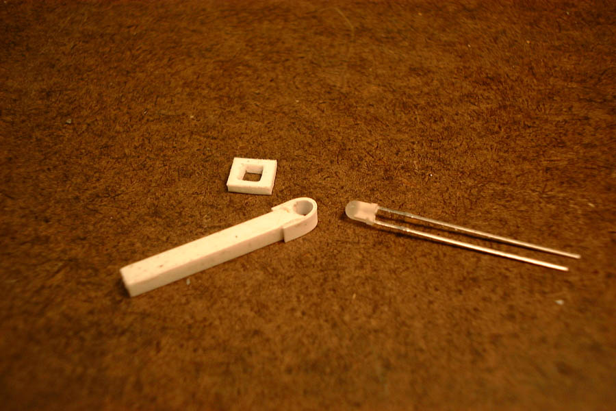
We start with a piece of 1/8 x 1/8 styrene about 2 inches long. Cut a slot down one side, with a depth of about a millimeter. I've found that this is easiest if you start with a scratch made with a knife, then widen and deepen it with a hacksaw blade. This slot will carry the wires that light the signal, and defines the rear of the post.
Make a semi-circular indentation at one end of the part, aligned with the slot as shown. Use a 1/8" diameter rat-tail file for this.
The prototype's long sunshade is a liability on the model, and we can make a shorter one that wll be quite adequate. Signal sunshades actually do vary in design!
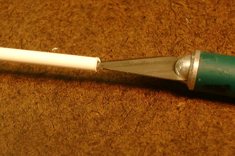
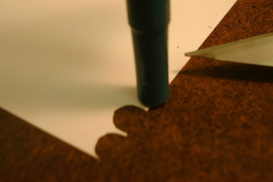
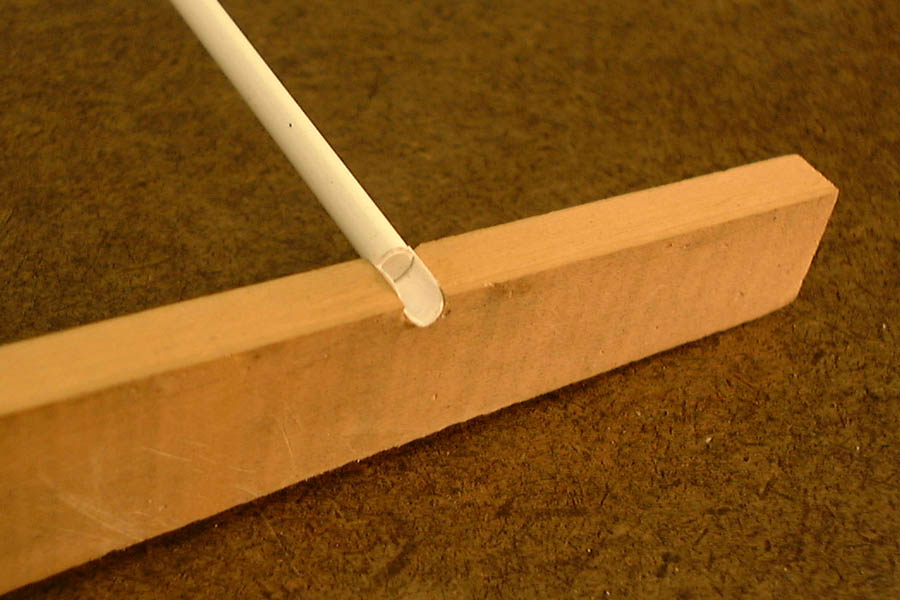
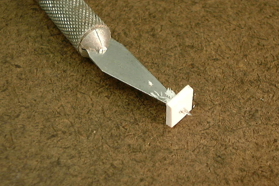
The sunshade is made from a semi-circular piece of thin styrene sheet (.005 or .010 thick) about 1/4" diameter. The easiest way to make this is to cut around a small object, in this case the back end of a ballpoint pen.
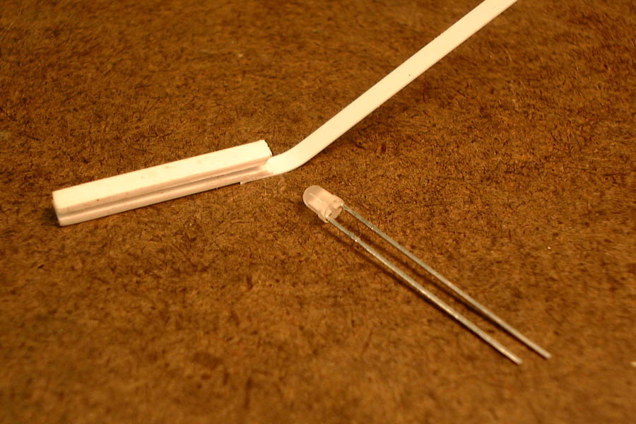
Returning to the main body of the signal, get a strip of 1/8 x .020 styrene. Bond it to the end of the post, adjacent to the filed-out notch. It should overlap with the body of the post about 3/16".
Place the LED into the indentation at the end of the post, and bend the styrene strip around it.
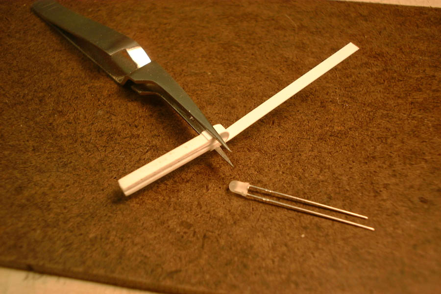
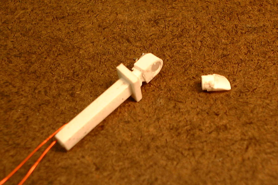
Just below the lower edges of the styrene wrapper at the top of the post, file a notch all around the post. Make the notch wider in the front of the post, and taper it down the sides.
When the solvent on the sunshade has set, the sunshade can be cut from the end of the tube. Cut it so that about 1 millimeter of tube extends beyond the sunshade. This assembly is delicate, so cut it by rolling the tube gently under a knife blade.
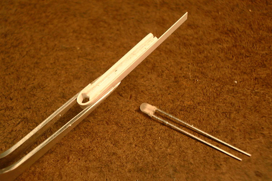
Prepare the LED by trimming its leads very short (about 1/16"). Tin each lead with a soldering iron, taking care to move quickly so as not to overheat the body of the component. Tin the wire ends also, and make a U-bend in the end of each. Then attach the wire ends to the LED leads. Allow the LED to cool down after attaching the first wire.
Attach the completed sunshade to the face of the post with a small amount of solvent. This bond will have only a small amount of surface area, so set it aside to develop its full strength before proceeding.
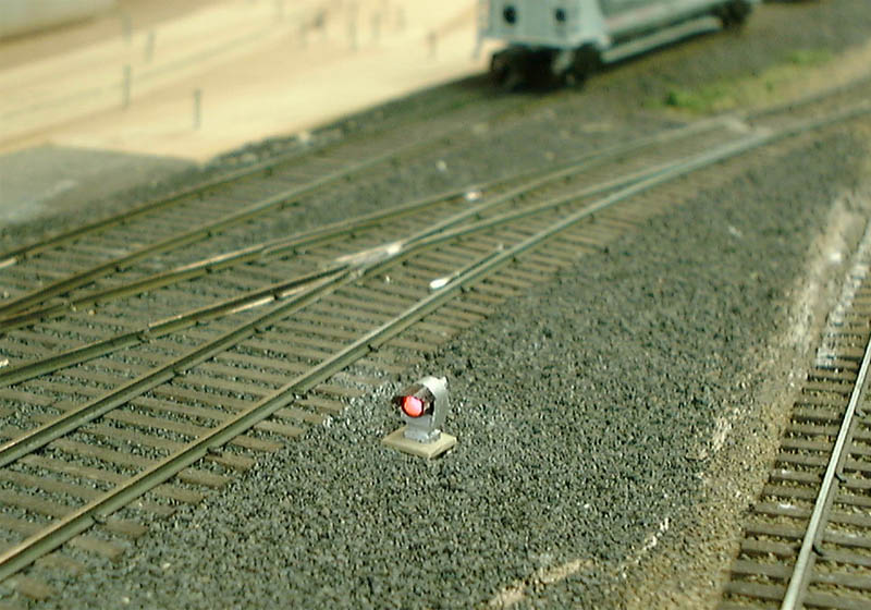
The signal is now complete.
...and also green.
If everything looks satisfactory, remove the base and paint it a suitable weathered-concrete color.
Put a small drop of cyanoacrylate cement on the side of the LED and press it into the signal head.
Experience has shown that the styrene body of the signal will glow with light from the LED. To prevent this, paint the signal head and the rear of the unit with black latex house paint. Paint the sunshade with normal black hobby paint. A dark grey shade actually seems to present the best appearance.
Overpaint the body of the signal first with white, then silver. The white coat is used because silver paint has poor hiding power over the black undercoat.
Install the base by sliding it up the signal post, making sure the wires are pressed into the slot at the back. Bond the wires in place with a little cyanoacrylate, and bond the base so that it sits just under the notch in the post, by applying solvent from below.
Drill a hole for mounting the signal at a slight angle, so that the "base" is placed level. This will set the head of the signal at a slightly upward angle, so the light is presented correctly to the engineer of an approaching train.